ARCHITECTURAL SERVICES
A. Architectural drawings, schedules, and technical specifications
B. Utility drawings
C. Sewer and drainage drawings
This article describes what is needed to prepare a design accustomed to the requirements of a client. It does not have any relationship to our standard prefab designs which have already been designed, engineered, and drafted. This article is solely intended for the client who wishes to have a design made and a unit built according to his requirements.
Our company offers the possibility to render design services which may include architectural drawings and/or structural calculations for a design to your requirements and/or a design following your sketch or modifications to one of our standard designs. We offer a variable design package that can be tailored to fit your wishes and requirements, divided into several stages. Very rarely, if not at all, will architects offer free-of-charge services. They will offer you a design against a certain architectural + structural design fee (if needed). We are not much different, except that we will refund the full architectural design fee if a fabrication order materializes. Structural design fees will not be refunded. Our design fee depends on the number of design stages we will be involved in. You may review these stages in the summary below. We would be happy to provide several references of clients for whom we were engaged in the preparation of a design package.
Our company not only builds prefab houses but also renders design services which may include architectural drawings and/or structural calculations and drawings. If you wish, our team of architects and engineers is available to cooperate with your architect and/or engineer to review the design to match this with our typically in-house developed prefab system. We may also design according to your local circumstances, hence based on locally available building materials. We have so far successfully designed projects for Hawaii, Panama, several Caribbean islands, and islands in the Pacific and Northern Indian Ocean, whereas the client could obtain the full building license from the Building Authorities without any comments.
FOR THOSE WHO WANT TO KNOW IN DETAIL ABOUT OUR ARCHITECTURAL SERVICES (this article is available for downloading < contact us >
A. ARCHITECTURAL DRAWINGS, SCHEDULES & TECHNICAL SPECIFICATIONS
You may be interested in having us engaged in one of the following services;
♦ have a design prepared from scratch,
♦ We prepare a design based on your sketch or ideas,
♦ have one of our standard designs modified to your wishes and requirements,
♦ wish to buy one of our existing standard designs for self-build, either in Bali and its surroundings or in any other country.
In practice a design project is divided into several stages, as follows:
STAGES OF A DESIGN PROJECT
Stage a: Project initiation (setting up the Program of Requirements, preparation of a Scope of Work,)
Stage b: Schematic design (sketch plan) and conceptual design.
Stage c: Pre-design. including a site plan (if so required by the building authorities)
Stage d: Basic design
Stage e: Detailed design + 3-D render (if required)
Stage f: Construction drawings + re-assembly manual + technical specifications. (check with the Excel sheet)
Stage g: Tender (invitation to tender, bid documents, and evaluation of bids) (*).
(*) This stage is only required if a client wishes to invite several contractors for a quotation.
STAGE a.
a-1. Program of Requirements
Design and/or construction projects are complex and affected by a maze of rules and regulations. A Program of Requirements (POR) is a document used in a design-build and purchasing process. An optimal construction process starts with a detailed Program of Requirements. The PoR lists the customer’s wants and needs. A Program of Requirements is aimed at creating a clear framework for everyone involved so that they all know which criteria must be met and to enable performance to be measured. As a result, the PoR is an important guideline for designers and builders to ensure that the desired result is achieved.
A building process involves lots of different parties, including architects, engineers, manufacturers, suppliers, government authorities, and sub-contractors The Program of Requirements provides guidance for all those involved in the construction process and is a XXX part of a project.
a-2 Scope of Work
A Scope of Work (SOW) is a formal document that defines and clarifies the work to be completed by a designer and/or a contractor during a construction project. It serves as a blueprint for the project and outlines the specific tasks, materials, and timelines that will be involved in completing the work.
An SOW is a document that outlines the objectives, deliverables, and expectations for a particular project. It serves as a legal agreement between two parties, detailing the scope and terms of the agreement that must be met to complete the project. This document also establishes how everyone will work together to get the job done.
An SOW should include:
• A description of the work to be done
• The deliverables that will be provided by the contractor
• The timeline for the completion of the work
• The budget for the project
The SOW is an important tool for all parties involved in a construction project, as it helps to ensure that everyone is on the same page regarding the scope of the work to be completed. It can also help to avoid potential disputes or misunderstandings down the road. In short, an SOW is essential for ensuring that all parties involved in a construction project are clear on what needs to be done, and when it needs to be done.
STAGE b.
Schematic design and conceptual design.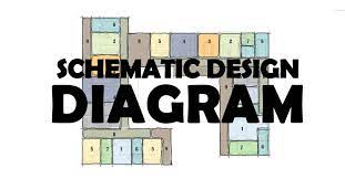
A schematic Design is the first phase of the architectural design process. At this stage, our design team begins to describe the architectural elements of the project
The team takes the Program of Requirements (refer to paragraph A-1 and translates it into an architectural and spatial design. Most of us explore many ideas in this phase to achieve the best possible design solutions.
Two important components for a successful schematic design phase are site analysis (refer to XXXX) and programming. Both the building program and location have significant implications in the design process, so it’s important to have a solid understanding of these foundational components at this stage.
The conceptual design is the result of the tasks undertaken by our architects and engineers during the development of the schematic design.
STAGE c.
Pre-design 
c-1 pre-design
Pre-design is the phase of analysis that occurs after some form of funding is available and before the actual design begins. During the pre-design phase, studies are done to analyze space requirement issues, the constraints and opportunities of the proposed site, and the approximate cost versus the available budget. The amount of funding available in the pre-design phase often varies and is a critical factor in determining which studies take precedence.
c-2 Site plan
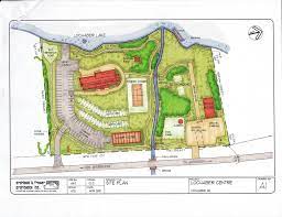
A site plan is a plan that provides overall guidance. It is a type of planning that pertains to the physical development of an area dedicated to the project over the long term, usually covering a time frame of about 20 to 25 years or longer into the future. A master plan is often required by the local building authorities to review the intentions of the developer. A site plan shall be developed and designed such that it adheres to the local regulations about building space, type of buildings, and utilities, A site plan shall include boundaries for existing and proposed parcels. if any; natural landforms and other site resources; site limitations; and other conditions affecting acquisition or development
A site plan shall include, but not be limited to showing the proposed location, land borders, building footprints of buildings and utilities, paths and roads, access, setbacks, stormwater drainage, electricity poles, and sometimes landscaping A site plan layout is often required by local authorities for obtaining permits and approvals, and it serves as a basis for construction and engineering. A site plan layout should reflect the site conditions, the project requirements, and the design standards.
STAGE d.
Basic design
A basic design focuses on the results obtained from stages A through C, This design is much more detailed and will give the client a clear view of how the prefabricated structure will look.
STAGE e.
e-1 Detailed design
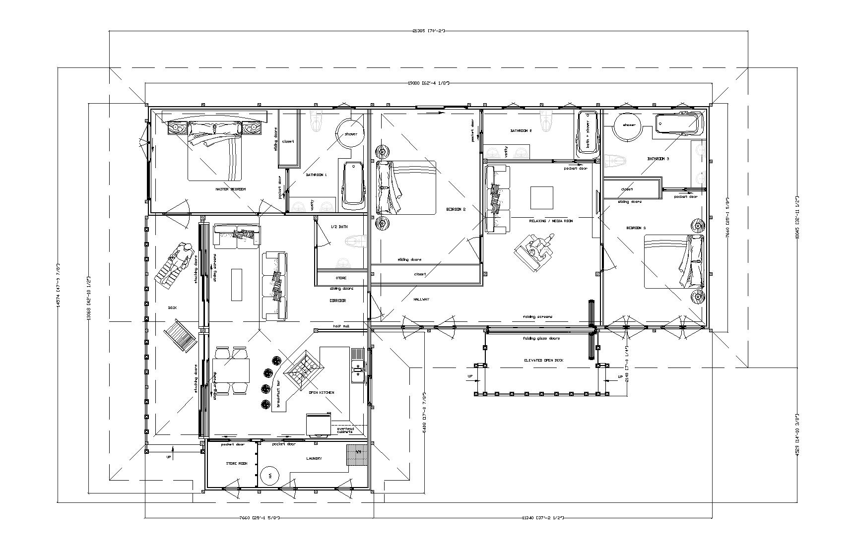
Detailed design example
A detailed design is the sum of stages b, c, and d concerning the construction details, the characteristics of the materials, and the construction methods of the project. It is an integral part of the project, and its purpose is to cover every construction aspect of the project, until its delivery.
The implementation of the detailed design is carried out by a team of architects and engineers, whose design follows a framework of clarity and simplicity to be fully understandable to all involved parties of the project (Client, architects, Engineers, Subcontractors, and Suppliers). The Project Manager directs and coordinates the design team to gather all the required information, channel them to the involved parties, and effectively link the team with the Client.
e-2 Render

Rendering is the process of creating a realistic image of a future house structure or space. Rendering takes a project designed in a modeling tool such as SketchUp (what we use) and transforms it into a 3D visualization. These outputs, such as images or sometimes animations, can be highly realistic and detailed, accounting for all aspects of the physical design or just impressionistic depictions of the design concept. A render will give a client a real feeling of how their house will look when it has been built.
STAGE f.
Construction drawings, re-assembly manual, and technical specifications
f-1 Construction drawings
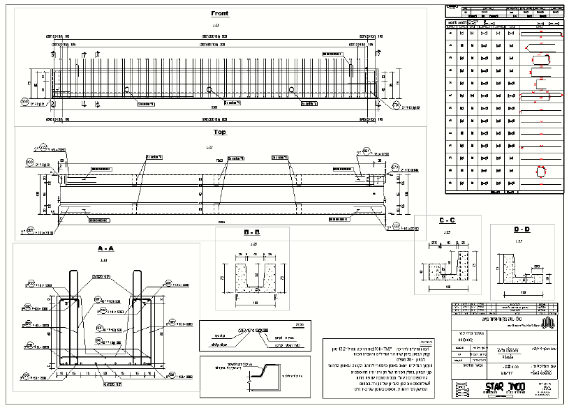
A detailed construction drawing, also called a "shop drawing" is required for the fabrication of the building elements. The shop drawings normally show more detail than the construction documents. It is drawn to explain the fabrication and/or installation of the items to the production crew or installation crews. The style of the shop drawing is usually very different from that of the architect’s drawing. The shop drawing’s primary emphasis is on the particular product or installation and excludes notation concerning other products and installations unless integration with the subject product is necessary.
f-2 Re-assembly manual
A re-assembly manual will be issued to help and assist the client or contractor with the re-assembly of the prefabricated members and parts. Each fabricated part is numbered on the manual and instructions are given on how to connect one part to another. All fixtures are part of the re-assembly package and cut to length at our factory. Only a little DIY experience is required to reassemble our units.
f-3 Technical specifications
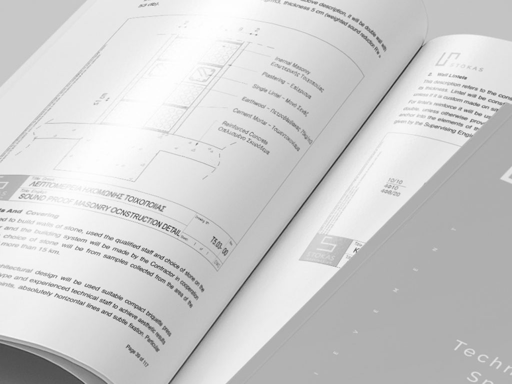
A technical specification is a description of the dimensions, construction, workmanship, materials, etc., of work done or to be done on a project, prepared by our company. A very prescriptive specification at a tender stage will ensure that the client has a high degree of certainty about what will be delivered. At the tender stage, the specification serves as an essential reference guide for contractors looking to price up a job. A technical specification document describes in words what cannot be visualized or explained on a drawing. The use of a standard classification system, such as the AIA is used by us and should remove any potential for confusion or ambiguity. A technical specification is always to be read as an integral part of the whole project and describes in detail what comes first: the specification or the drawing in case of a contradiction.
STAGE g.
Tender (this stage is only for clients who wish to invite one or more contractors for a quotation on the project to be able to compare prices)
A tender is issued as a request for participation in a project. Tendering is the procedure through which interested parties are invited to bid for a project that must be completed within a specific timeframe. Read more < tender >
B. UTILITY DRAWINGS
B-1 Electrical drawings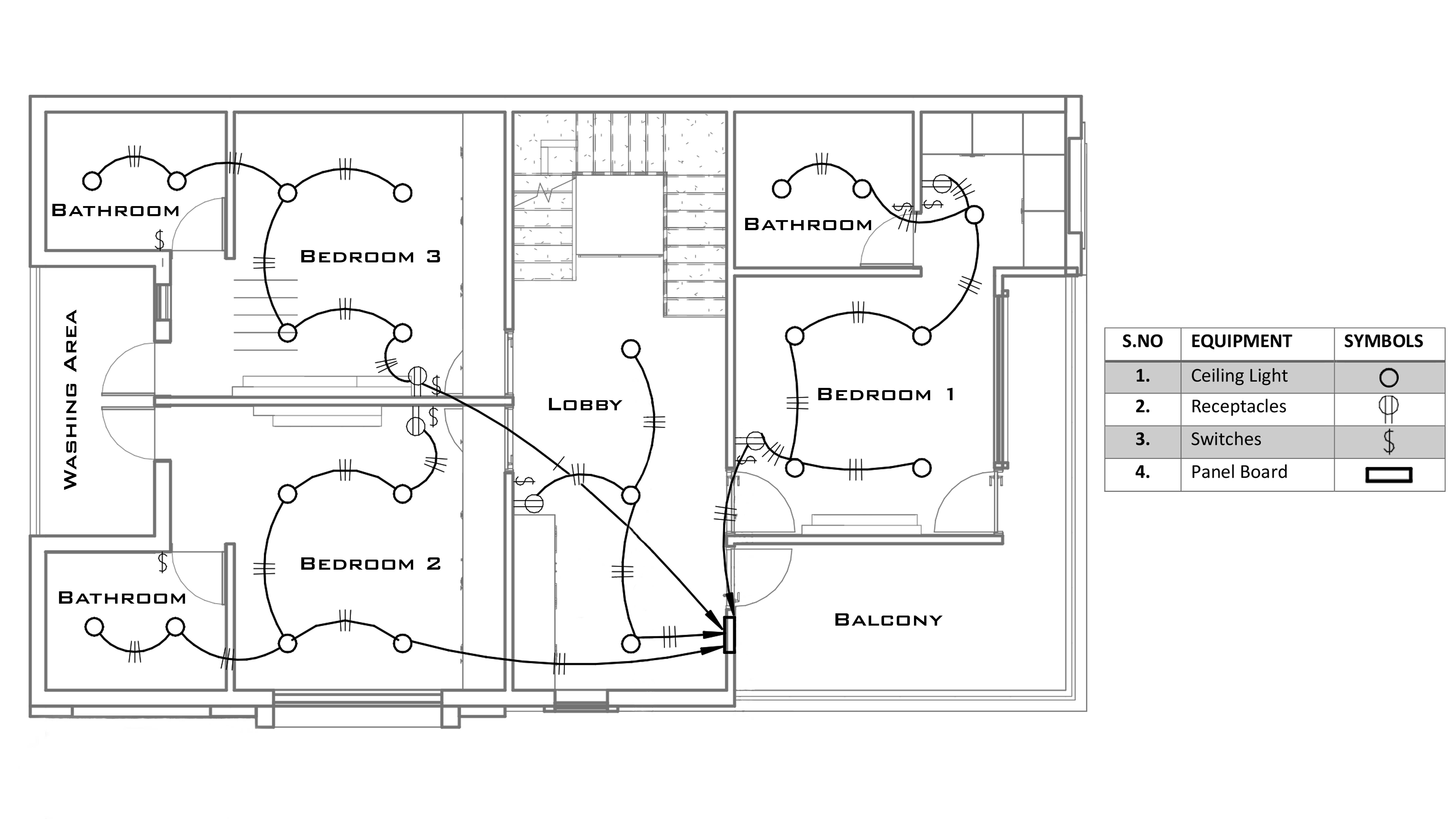
We will be able to design a flawless electrical system for your home with accurate electrical drawings. Our drawings which are very accurate help electricians to easily install the cables, sockets, switches, and fittings. Be alerted that without electrical drawings it is very likely that electricians may end up with a faulty installation. Our electrical drawings will be prepared as per the client's requirements ensuring safety. It is not necessary to invest in employing professional electrical engineers for the preparation of the electrical drawings. We have all the experience available and will be able to cut down on expenses.
Except for a few countries we are not allowed to install cables, sockets, switches, and fittings, however, our design drawings will be fully accepted and approved. A local electrician will be able to understand our drawings and install the system.
B-2 Plumbing drawings
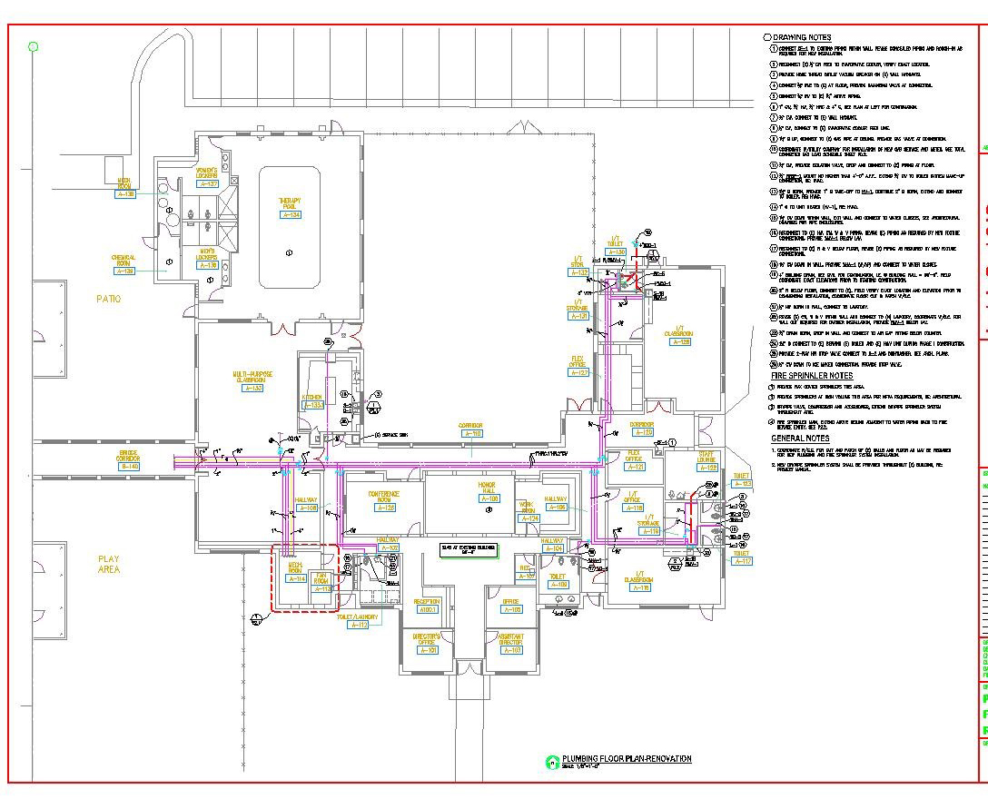
Plumbing is any system that conveys fluids for a wide range of applications. Plumbing uses pipes, valves, plumbing fixtures, tanks, and other apparatuses to convey fluids. Waste removal and potable water delivery are among the most common uses for plumbing, but it is not limited to these applications. In the developed world, plumbing infrastructure is critical to public health and sanitation. Our company can design a modern plumbing system and can also install it.
C. SEWER AND DRAINAGE DRAWINGS
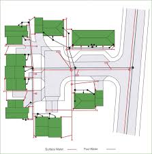
Drainage is the natural or artificial removal of surface water and subsurface water from an area with excess water, most of the time caused by rainfall. The internal drainage of most soils is good enough to prevent severe waterlogging, but many soils need artificial drainage to prevent the soil from getting wet.